
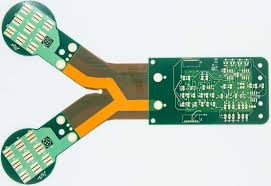
Rigid Flex PCBs Are Constructed
Rigid flex boards are designed in 3D, which means they can be twisted and folded to create the final product. This allows for greater spatial efficiency and reduced assembly costs. It also makes it easier to integrate mountable components into the PCB, making it ideal for applications that require a compact or flexible electronic product.
While both rigid flex board are durable, the construction differences between them determine their durability in different ways. Rigid PCBs are thicker and offer more mechanical stability, while flex materials allow them to absorb vibrations and other environmental elements without breaking or failing.
Depending on the application, either one or both of these qualities may be necessary for your design. For example, if your circuit board will be subjected to dynamic flexing during operation, you’ll need a rigid flex that is designed to withstand repeated bending and flexing without mechanical failure. Rigid flex board designs can include stiffeners to provide mechanical support to the flex sections of the circuit board, which can reduce the risk of circuit traces being damaged during flexing and bending.
How Rigid Flex PCBs Are Constructed
In addition, rigid flex boards are often used for high-reliability applications where the circuit board must be subjected to shock or extreme vibration conditions. The combination of rigid and flex circuitry in the rigid flex board provides better signal integrity, a more compact package size and weight reduction, and the ability to accommodate mounting components in both rigid and flex sections.
The rigid-flex construction process starts with the creation of a rigid-flex board design in an electronic PCB software program, like Altium Designer(r). This design program will incorporate a combination of rigid and flex circuit layers, with plated through holes (PTH) that connect both the rigid and flexible portions of the circuit board.
Once the rigid-flex circuit board design is complete, it’s ready for manufacturing. During the fabrication process, the rigid-flex circuit board will undergo a series of steps to produce a finished product, including etching, drilling, copper plating, cover lay application, and stiffener application.
During the etching process, both sides of the circuit board are etched using precision chemical and mechanical processes. The circuit traces on the rigid-flex circuit board are then drilled using various systems and techniques, including laser drilling, to form the required pad and via patterns. The circuit traces are then plated with copper to establish the electrical interconnects between rigid and flex areas.
The next step is to apply the cover lay material, which includes a layer of adhesive. Once the cover lay is applied, it is laminated to both the rigid and flex circuit boards to ensure proper adhesion. Stiffeners are then applied, if needed, to provide mechanical support to the flex sections. Finally, the flex circuits are cut using specialized blanking knives or hydraulic punching methods. The final product is then electrically tested and verified to ensure that the isolation, continuity, quality, and performance meet the circuit board design specifications.